Time domain analysis
You can create various maps with the following parameters.
- Activation time
- Rise time
- Peak time
- Peak amplitude
- Repolarization time
- Peak to repolarization time
- APDxx
- Decay τ
- Upstroke velocity
- Diastolic interval
- Peak interval
- Alternans
- APDxx alternans
Select [Time domain analysis] from the [Analyze] menu.

On this dialog, a map can be created like below.
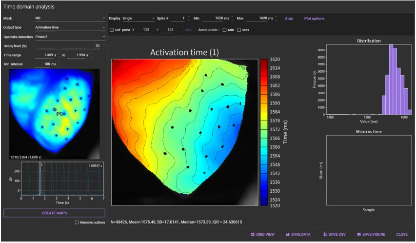

(1) Mask
Select the map creation area from “All pixels”, “Mx (mask)”, “Rx (region)”, "Cx (circle)".
(2) Output type
Select the type of map you want to create.
(3) Upstroke detection
Select detection method for activation time from “Fmax/2”, “Fmax” and “max(dF/dt)”.
(4) Decay level (%)
Set recovery % from the peak to baseline.
(5) Time range
Set a time range. Peaks outside this time range are ignored.
(6) Min. interval
Set a minimum time span between two peaks. This setting is used for automatic detection of peaks.

(7) Image display
Shows the same data as the main screen.
The following mouse operations are possible on the image.
| Operation | Description |
|---|---|
| Scroll mouse wheel | Enlarge/reduce horizontal waveform size. |
| Mouse drag a point | Light intensity change at the specified pixel is displayed in (8) . |

(8) Wave display
Display light intensity change in the pixel specified in (7) .
The following mouse operations are possible on the waveform.
| Operation | Description |
|---|---|
| Scroll mouse wheel | Enlarge/reduce horizontal waveform size. |
| Mouse drag on waveform/Click on waveform | Move frame. |
| Hold “Ctrl” key and drag mouse pointer to right | Select time range of waveform. |
| Hold “Ctrl” key and drag mouse pointer to left | Deselect time range selection for waveform and select all ranges. |
(9) CREATE MAPS
Create one map for each peak in the selected time range.
Click this button to automatically detect peaks and display peak numbers at the top of each waveform.


(10) Display
Select display mode from “Single”, “Average” and “Difference”.
- Single : Display a map for each peak.
- Average : Display average map of all peaks
- Difference : Create a difference map between the two peaks
(11) Spike
Specify number of peak (action potential or calcium transient) to display.
(12) Min
Specifies minimum value to be displayed in color.
(13) Max
Specifies maximum value to be displayed in color.
(14) Auto adjustment
Click to set min and max to optimal values.
(15) Plot options
Click to open plot options. Color map (palette) can be changed.

(16) Ref. point
Set the point where value=0 so that all data can be mapped to the same color scale. This has no effect for time span values (e.g. APD).
(17) X
Displays the X coordinate of the reference point. You can change this value.
(18) Y
Displays the Y coordinate of the reference point. You can change this value.
(19) Min
Set the “ (17) Ref. point” position to the min. value position.
(20) Annotations: Min
Annotate minimum value points.
(21) Annotations: Max
Annotate maximum value points.
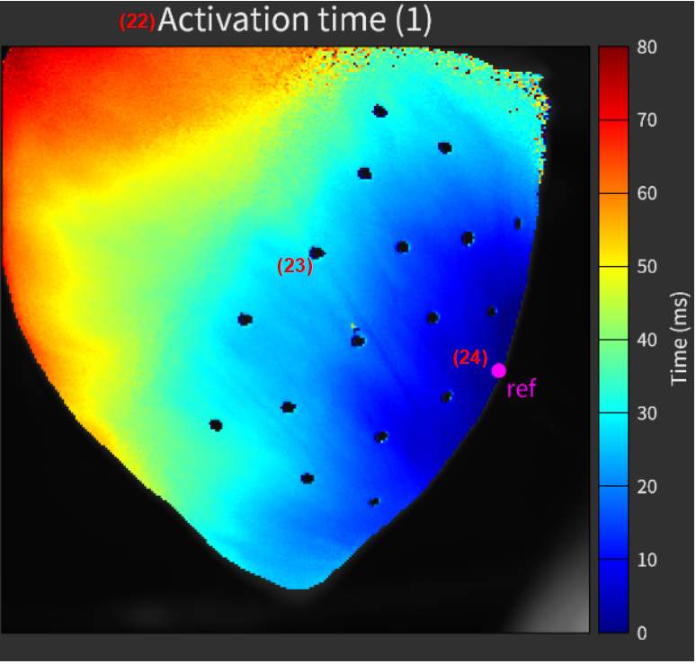
(22) Title and spike
The image title and spike # are automatically displayed.
(23) Map
A map created for each peak is shown here.
The following mouse operations are possible.
| Operation | Description |
|---|---|
| Scroll mouse wheel | Enlarge/reduce horizontal waveform size. |
| Mouse move over image | Coordinates and values are displayed on the top left of the map. |
(24) Ref. point
Select “ (16) Ref.point” to display the point on the image. Mouse drag the point where value=0 so that all data can be mapped to the same color scale.
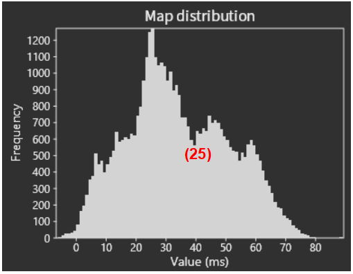
(25) Distribution
Displays a histogram showing the relationship between values and number of pixels. Scrolling mouse wheel enlarges/reduces size of histogram.
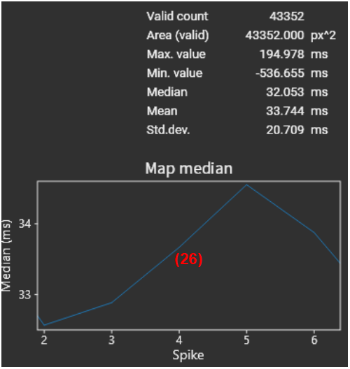
(26) Mean vs time
Displays mean values for each peak.

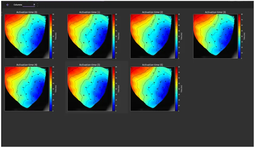
(27) GRID VIEW
Display multiple created maps in a grid. The number of columns can be changed with "Columns".
(28) SAVE VALUES
Save data to a binary file (*.dat).
(29) SAVE FIGURE
Export map as an image file. Click to open “Figure editor”. See “Save image (figure editor)” for details.
(30) SAVE STATISTICS
Save numerical values of displayed map to a CSV file.
(31) CLOSE
Close this dialog.