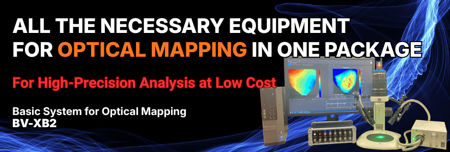
Basic System for Optical Mapping BV-XB2
- Want to start optical mapping, but find it hard to secure the budget?
- Need to optimize the introduction cost for limited use?
- Not sure which peripheral devices to choose and how to configure them?
To solve these challenges in the research field, we have launched the basic system for optical mapping, BV-XB2 .
BV-XB2 is a starter kit that lets you begin optical mapping on a low budget. It is an all-in-one system that covers a high-speed camera and analysis software, plus an excitation LED light source, a multifunction electrical stimulator, and the optics. If you already have equipment such as a perfusion system, you can start experiments right after installation.
With high-speed sampling up to 1,572 fps*, BV-XB2 records membrane potential propagation and calcium concentration changes in detail. After acquisition, the dedicated software enables seamless data analysis as well as the creation and output of various maps.
This product is for research use only (RUO).
* At 128 x 128 pixel setting
Standard System Configuration
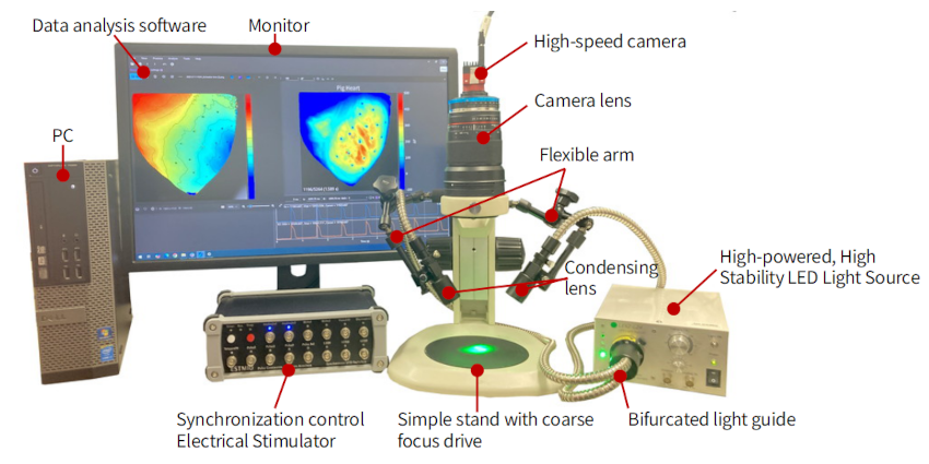
The system configuration is shown in the table below. We can also propose a custom system with modified parts to match your budget and the experiments you have in mind.
| Component | Details |
|---|---|
| High-Speed Camera | Allied Vision Alvium 1800 U-052m |
| Computer | PC, LCD monitor |
| Acquisition / Analysis Software | Optical Mapping Data Analysis Software BV Workbench |
| Optics | Camera lens, simple stand with coarse focus drive, bifurcated light guide, 2 condensing lenses for light guide, 2 flexible arms |
| LED Light Source | High-powered, High-Stability LED Light Source LEX5 |
| Synchronization Control / Electrical Stimulator | Multifunction Electrical Stimulator ESTM10A |
(Note) The perfusion system, stimulating electrodes, recording electrodes, and ECG amplifier are not included. They must be prepared separately.
Applications
-
Imaging Method
- Voltage imaging using voltage-sensitive dyes
- Calcium imaging using calcium indicators
- Intrinsic fluorescence signal imaging derived from flavoproteins or hemoglobin
- Imaging using fluorescent proteins such as FRET, GCaMP, GEVI
-
Animal samples
- Langendorff-perfused heart
- Cultured cardiomyocytes
- In vivo brain
- Brain / Spinal cord slices
- Cultured neurons
- Organoid / Spheroid
System Features
1. Start Experiments Right After Installation, with No Setup Hassle — All Necessary Equipment in One Set
Because all the equipment needed for experiments is bundled into a single package, there is no need to select and procure peripheral devices individually. This reduces setup time and provides an environment where you can focus on the research itself.
2. Start Optical Mapping Easily on a Limited Budget — Lower Price Than Before
By adopting a general-purpose high-speed camera and simple optics, we have achieved a significantly lower price than our previous systems.
While the S/N ratio is lower than that of higher-end models, the analysis software, LED light source, and electrical stimulator are shared with the higher models, so you can conduct research with a professional-grade workflow at an affordable price.
3. Record Action Potential Propagation in Detail — High-Speed Imaging at Over 1,000 Frames/Second
To accurately capture action potentials that change on a millisecond scale, a speed of 1,000 fps (1 ms/frame) or higher is essential.
This system enables high temporal resolution through ROI (Region of Interest) partial readout. It depicts neural and cardiac propagation patterns in detail, enabling highly reliable data acquisition.
| Frame Rate | Resolution | Sensor Active Area |
|---|---|---|
| 165 fps | 816 x 624 pixels | 7.3mm x 5.6mm |
| 306 fps | 512 x 512 pixels | 4.6mm x 4.6mm |
| 1,015 fps | 256 x 256 pixels | 2.3mm x 2.3mm |
| 1,295 fps | 192 x 192 pixels | 1.7mm x 1.7mm |
| 1,572 fps | 128 x 128 pixels | 1.2mm x 1.2mm |
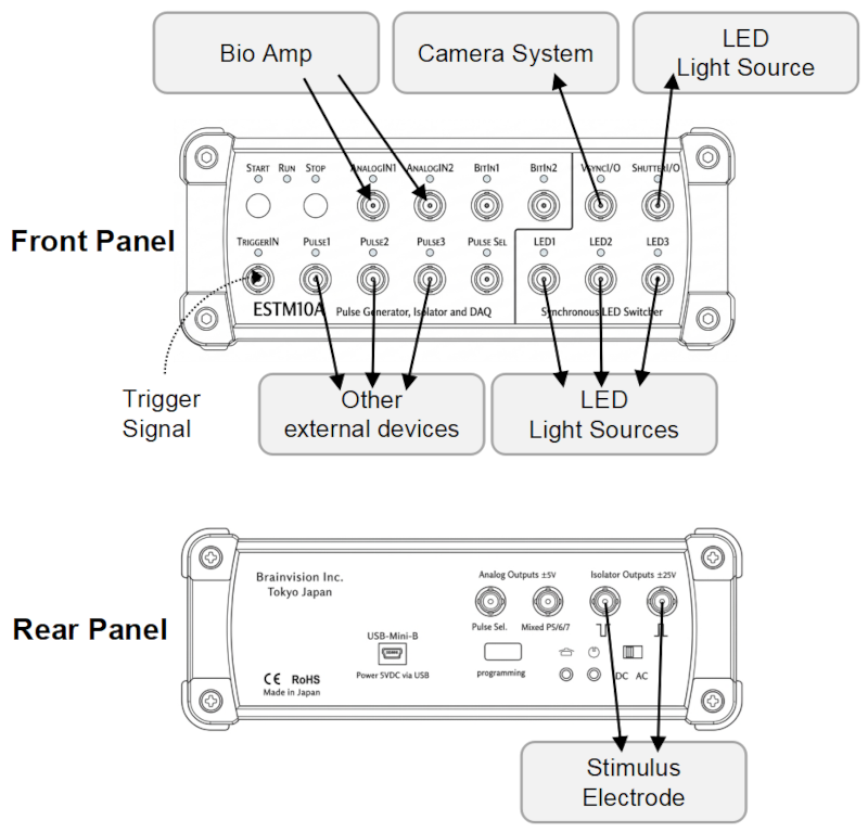
4. Simple Setup by Just Connecting — Automated Synchronization Control and Stimulus Pattern Creation
By simply connecting each device to the ESTM10A, which acts as the command center, camera acquisition, light source illumination, pacing, and ECG recording can be automatically synchronized.
This reduces the stress caused by complex wiring and settings and supports stable, error-free experiments.
The high-speed camera settings and data acquisition are handled by BV Workbench.
-
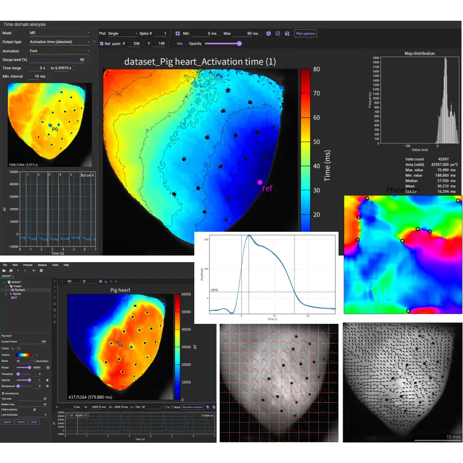
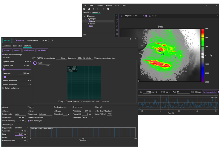 Camera control and acquisition software (BV Workbench)
Synchronization of camera acquisition, light source illumination, and stimulation is handled by the control software for the ESTM10A.
-
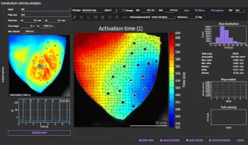
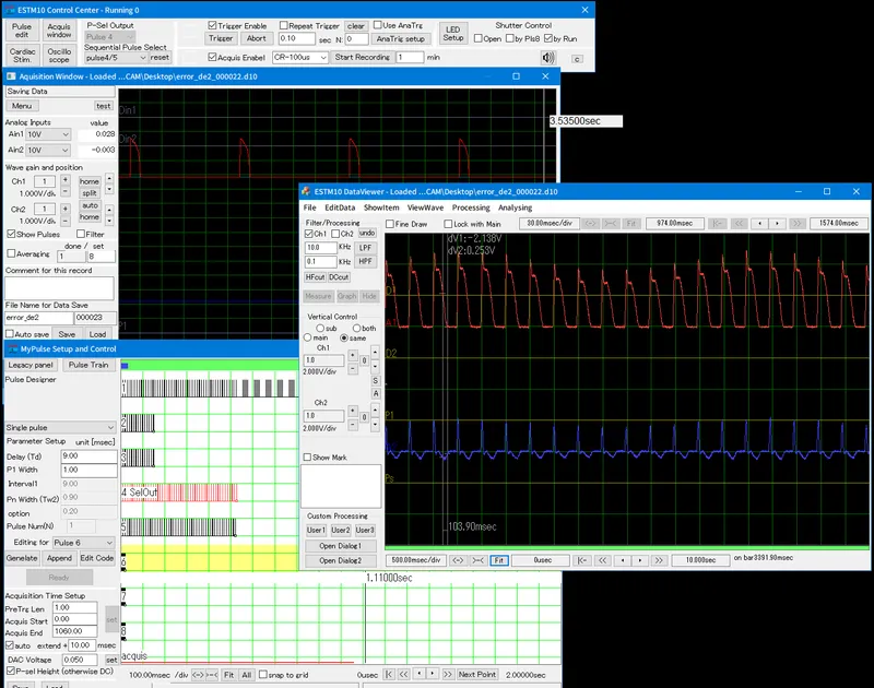 Software for synchronization control, electrical stimulation
and analog recording (ESTM10A)
Software for synchronization control, electrical stimulation
and analog recording (ESTM10A)
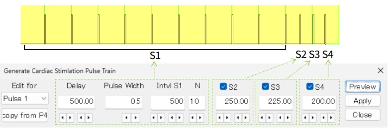
5. Pacing Is Also Possible — Pulse Output Function
The multifunction electrical stimulator ESTM10A has an output terminal with a built-in isolator. By connecting stimulating electrodes, electrical stimulation of animal samples is also possible.
It also provides modes for creating stimulus patterns such as S1-S2 and S1-S2-S3-S4, which are used when applying electrical stimulation to the heart.
Product information
- Multifunction Stimulator ESTM10A
- ESTM10A
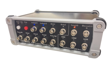
ESTM10A is an all-in-one system with built-in functions often used in biological imaging experiments and electrophysiology experiments, such as stimulus pulse output, acquisition timing control for camera, lighting control for LED light sources, biological signal recording, and digital oscilloscope, etc.
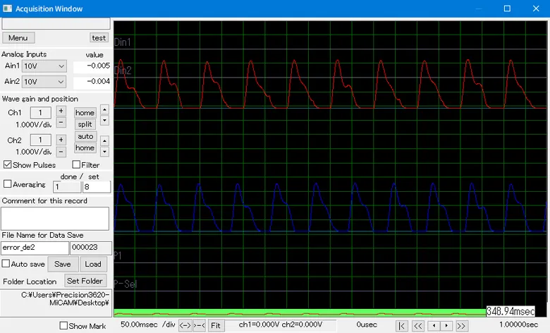
6. ECG Recording Synchronized with Image Data Is Also Possible — Analog Recording Function
The multifunction electrical stimulator ESTM10A is equipped with 2 channels of analog input. By connecting an ECG amplifier (sold separately), ECG recording synchronized with image data is also possible.
7. High-Precision Data Analysis and Map Creation with Simple Operation — Dedicated Data Analysis Software
Data analysis uses BV Workbench, the data analysis software bundled with the higher-end models. You can easily output high-resolution map images for use in scientific papers and presentations.
Product information
- Optical Mapping Data Analysis Software
- BV Workbench
BV Workbench Ver.4 is the latest version of data analysis software developed for optical mapping and calcium imaging of the brain and heart.
In addition to data files acquired with Brainvision's MiCAM imaging system, it is also possible to open 16-bit TIFF files acquired with cameras and imaging systems from other companies.
8. Adds No Noise to Biological Signals — Stable LED Light Source with Minimal Fluctuation
The system adopts "LEX5," an LED light source dedicated to high-speed imaging. A feedback mechanism that constantly monitors brightness and suppresses flickering prevents unnecessary noise from entering the data. Because brightness fluctuation is kept below 0.3% even during 30 seconds of illumination, even subtle signal changes can be clearly distinguished.
-
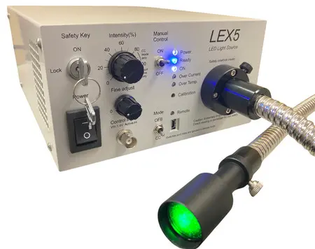 High-powered, high-stability LED light source LEX5
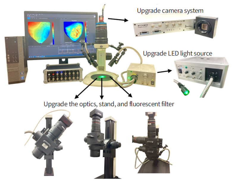
9. Add Functions Later as Your Research Progresses — Flexible Customization Supported
You can upgrade each part later according to changes in research direction or budget. Because the system can evolve flexibly to match future needs, you can use the equipment you have introduced for a long time without waste.
| Example of Request | Details | Example of Change |
|---|---|---|
| Improved S/N ratio | Change to a higher-end camera | Change to MiCAM03-N256 |
| Multi-wavelength recording | Expansion to a system for simultaneous recording of membrane potential and calcium transient |
Add a fluorescence splitter and fluorescence filters Add a light source or change to LEX9 |
| Change of target animal | Change to a lens suitable for guinea pigs, rabbits, etc. | Change to a low-magnification lens |
| Easier focus adjustment | Add a fine focus adjustment function | Change to a motorized focus drive |
Specifications
| BV-XB2 System | |
|---|---|
| Name | Optical Mapping System BV-XB2 |
| Model | BV-XB2 |
| Standard System Configuration |
· Camera head Alvium 1800 U-052m · Data analysis software BV Workbench · Camera lens + simple stand · Multifunction electrical stimulator ESTM10A · High-powered, high-stability LED light source LEX5 · 1 bifurcated light guide + 2 condensing lenses · 2 flexible arms for holding light guides · Computer · LCD monitor · Cables |
| Camera Head | |
| Image Sensor | Sony CMOS IMX426 (1/1.7 inch) |
| Resolution (H x V) | 816 x 624 |
| Active Image Area (H x V) | 7.3mm x 5.6mm |
| Pixel Size (H x V) | 9.0µm x 9.0µm |
| Shutter Mode | Global Shutter |
| Spatial Resolution and Maximum Frame Rate |
165fps@816x624 pixels 306fps@512x512 pixels 1,015fps@256x256 pixels 1,295fps@192x192 pixels 1,572fps@128x128 pixels |
| Quantum Efficiency | 73% (@529nm) |
| Dark Noise | 21.8 e- |
| Saturation Capacity | 100,000 e- |
| Pixel Bit Depth | 12bit |
| Interface | USB3 Vision |
| Lens Mount | C-mount |
| Dimensions (L x W x H) / Weight | 38mm x 29mm x 29mm / 60g |
| Synchronization Control / Electrical Stimulator ESTM10A | |
| Input Terminals | Analog (2ch) / Bit (2ch) / Trigger (1ch) |
| Output Terminals | Pulse (4ch) / LED (3ch) / Isolated (1ch) / Analog (2ch) |
| I/O Terminals | V-sync (1ch) / Shutter (1ch) |
| Digital Input Terminal | Input voltage: 0V/5V |
| Digital Output Terminal | Output voltage: 0V/5V, Output current: 5mA |
| Analog Input Terminal | Input voltage: 10V |
| Analog Output Terminal | Output current: 5mA |
| Isolator Output Voltage | Output voltage: ±25V |
| Analog Output Voltage | Output voltage: ±5V |
| Dimensions / Weight | 245mm (W) x 90mm (H) x 180mm (D) / 1.3kg |
| LED Light Source LEX5 | |
| Center Wavelength | 530nm |
| Number of Built-in LEDs | 1 |
| Mountable Filter | 25mm fluorescence filter x 1 |
| Brightness Control (Manual) | Coarse 0–120% / Fine 0–10% |
| Brightness Control (Software) | 0–120% |
| Illumination Control |
Manual switch External signal input (> 1.4V) Software |
| Illumination Mode |
CC (constant current) mode OFB (optical feedback) mode |
| Brightness Drift during 30 s of Illumination | < ± approx. 0.3% |
| Optical Output Noise | < ± approx. 0.01% |
| Input Terminals |
BNC terminal (for illumination control) x 1 USB mini-B terminal (for software control) x 1 |
| Acquisition / Analysis Software | |
| Supported OS | Windows 11 |
| Recommended PC Specifications |
Minimum · Any Intel or AMD x86-64 processor · 8 GB of RAM · 400 MB of disk space for installation Recommended · Intel or AMD x86-64 processor with 4 logical cores and the AVX2 instruction set · 32 GB of RAM · NVMe solid-state drive · NVIDIA GPU |
| Optics | |
| Objective Lens | 24mm/1.4 camera lens |
| Lens Mount | C-mount |
| Stand | Basic stand |
| Focus Adjustment | Manual coarse dial |
| Light Source Light Guide | Bifurcated light guide + 2 condenser lenses |
| Light Guide Holding Mechanism | 2 flexible arms |
| Illumination Method | Oblique illumination |
| Supported Fluorescence Filter | 50mm fluorescence filter |
* This product is for research use only. * This product is made in Japan.