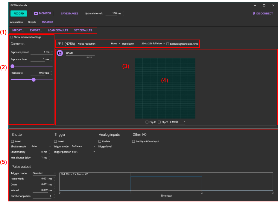
MiCAM03 acquisition setting
Click [MiCAM03] tab to open the tab page for MiCAM03 acquisition setting.
On this tab page, you can set the data acquisition settings for MiCAM03-N256.
1. Saving and loading settings
![]()
| IMPORT... | Load file (file extension: config) where acquisition setting condition is saved and change the setting. |
|---|---|
| EXPORT... | Save current acquisition setting condition in a file (file extension: config). |
| LOAD DEFAULTS | Load default setting saved with [SET DEFAULTS] and change the setting. |
| SET DEFAULTS | Save the current acquisition setting condition as the default setting. Next time you start up, the saved default settings will be used. |
2. Setting frame rate (exposure time)
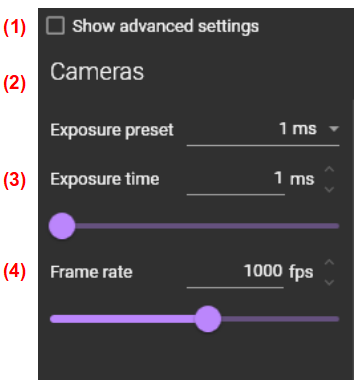
(1) Show advanced setting
The settings for advanced users are displayed. For MiCAM03, the settings for “Sequencer”, which can be used to control two kinds of LED light source for excitation, is displayed.
(2) Exposure preset
Select exposure time for one frame from the list. Minimum exposure time depends on number of pixels.
(3) Exposure time
Specify an arbitrary exposure time for one frame in microseconds. Please enter a number in the text box, or click arrow buttons next to the text box, or move the horizontal slide bar and specify it. Minimum exposure time depends on number of pixels.
(4) [Frame rate] will also be changed if the value is changed (Frame rate = 1000 / Exposure time).(4) Frame rate
Specify number of frames per second (fps). Please enter a number in the text box, or click arrow buttons next to the text box, or move the horizontal slide bar and specify it. Maximum frame rate depends on number of pixels.
(3) [Exposure time] will also be changed if the value is changed (Exposure time = 1000 / Frame rate).| Number of Selectable Pixels (HxV) | Maximum Frame Rate (fps) | |||
|---|---|---|---|---|
| NR Mode=OFF | NR Mode=ON (2 Times Avg) | NR Mode=ON (4 Times AVG) | ||
| 256x256 | Full Resolution | 1,818 | 1,923 | 1,031 |
| 192x192 | Square ROI | 2,941 | 3,125 | 1,695 |
| 128x128 | 5,263 | 5,556 | 3,333 | |
| 64x64 | 12,500 | 12,500 | 8,333 | |
| 256x128 | Horizontally Long Rectangle ROI | 3,333 | 3,448 | 1,887 |
| 256x64 | 5,882 | 5,882 | 3,226 | |
| 256x32 | 9,091 | 8,333 | 5,000 | |
| 128x256 | Vertically Long Rectangle ROI | 3,030 | 3,333 | 1,852 |
| 64x256 | 4,348 | 5,000 | 3,125 | |
| 32x256 | 5,556 | 7,143 | 4,762 | |
| 32x32 | 16 blocks | 2,381 | 2,632 | 1,724 |
| 15 blocks | 2,500 | 2,778 | 1,818 | |
| 14 blocks | 2,703 | 2,941 | 1,961 | |
| 13 blocks | 2,857 | 3,125 | 2,083 | |
| 12 blocks | 3,125 | 3,448 | 2,273 | |
| 11 blocks | 3,333 | 3,704 | 2,439 | |
| 10 blocks | 3,704 | 4,000 | 2,703 | |
| 9 blocks | 4,000 | 4,348 | 2,941 | |
| 8 blocks | 4,545 | 5,000 | 3,226 | |
| 7 blocks | 5,000 | 5,556 | 3,704 | |
| 6 blocks | 5,556 | 6,250 | 4,167 | |
| 5 blocks | 6,667 | 7,143 | 5,000 | |
| 4 blocks | 7,692 | 8,333 | 5,882 | |
| 3 blocks | 10,000 | 11,111 | 7,692 | |
| 2 blocks | 12,500 | 14,286 | 10,000 | |
| 1 blocks | 20,000 | 20,000 | 16,667 | |
The following (5) and (6) are displayed when [Show advanced settings] is selected.

(5) Monitor frame count / (6) Monitor frame index
This setting is for the function of LED sequencer pulse output, which is output from the terminals on the optional unit.
3. Number of pixels and camera gain
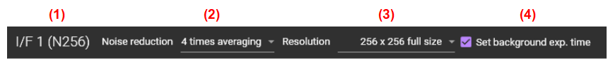
(1) I/F 1 (N256)
Displays camera interface number and camera name.
(2) Noise reduction
Select noise reduction mode to reduce noise. Specifically, by performing voltage reading of each pixel multiple times and averaging, photon shot noise and noise in the circuit are reduced, and S/N ratio is improved.
The maximum frame rate changes depending on combination of number of pixels and noise reduction setting. See “Number of Selectable Pixels and Maximum Frame Rate”.
| None | Noise reduction OFF |
|---|---|
| 2 times averaging | Noise reduction ON / 2 times averaging |
| 4 times averaging | Noise reduction ON / 4 times averaging |
(3) Resolution
Select number of pixels. In standard mode, only 256 × 256 pixels and 128 × 128 pixels can be selected. When [Option 2: Multiple ROI Readout for Higher Frame Rate] is used, other pixel setting and multi ROI setting can be selected.
The maximum frame rate changes depending on combination of number of pixels and noise reduction setting. See “Number of Selectable Pixels and Maximum Frame Rate”.
(4) Set background exp. time
Select to set exposure time of background image. “Background exposure time (ms)” box for entering exposure time is displayed in the area of 4.
4. Monitor screen and other settings
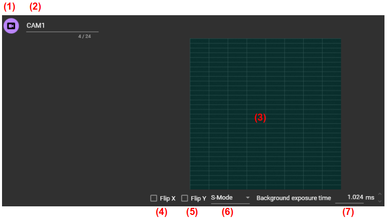
(1) Camera ON/OFF
Click to switch the camera ON/OFF.
 | Camera is ON. |
 | Camera is OFF. |
(2) Camera name
Camera name can be changed freely. Camera name is appended to saved data name.
(3) Monitor screen
When the [MONITOR] button is clicked, monitor starts and monitor image is displayed in this area. By right-clicking on monitor image, the following setting items are displayed.
| Show overlay | Not available |
| Capture background on start | When checked, background image is captured at start of every acquisition. One frame is acquired. When unchecked, background image used for previous acquisition is used as background image for newly acquired data. |
| Import background... | Not available |
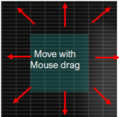
(Option 2 : Multiple ROI Readout Option)
Also, if you select anything other than 256 x 256 pixels from [Resolution], the region(s) for acquisition will be displayed on the monitor display. By dragging the region(s) with the mouse, it is possible to move along the grid line.
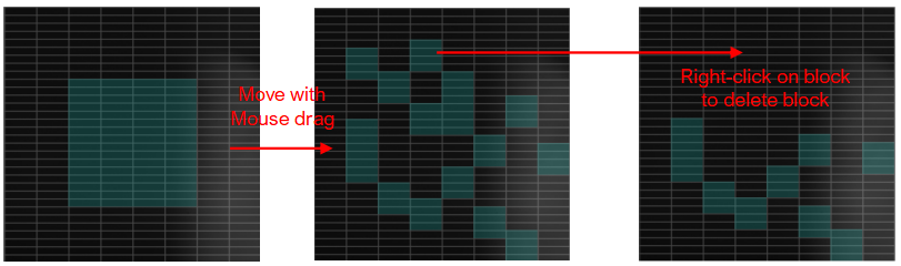
When 32x32x16, 32x32x8, 32x32x4 pixels are selected from [resolution], 32x32 blocks can be moved along the grid lines. You can delete the block by right-clicking on 32x32 block.
(4) Flip X
Flip an image horizontally (left and right)
(5) Flip Y
Flip an image vertically (up and down)
(6) S-Mode / D-Mode
Switch the number of full well capacity of the N256 camera.
| S-Mode | full well capacity 600,000 e- |
|---|---|
| D-Mode | full well capacity 3,000,000 e- |
(7) Background exposure time (ms)
This setting is displayed only when [Set background exp. time] is selected. Set exposure time of background image taken at timing of starting acquisition.
5. Settings for I/O signal
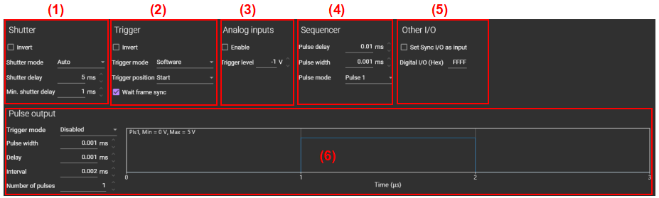
(1) Shutter
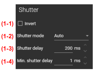
(1-1) Invert
| OFF | Operation shown in (1-2) [Shutter mode] (for using a light source made by Brainvision) |
|---|---|
| ON | Opposite operation shown in (1-2) [Shutter mode] (for using a third-party light source system) |
(1-2) Shutter mode
Controls shutter control signal (TTL) output for light source from the [Shutter] terminal on the front of MiCAM03 processor.
| Auto | During frame acquisition after pressing [Acquisition]/[Monitor] button: 5V output Others: 0V output |
|---|---|
| Open | When selected from the list box: 5V output |
| Close | When selected from the list box: 0V output |
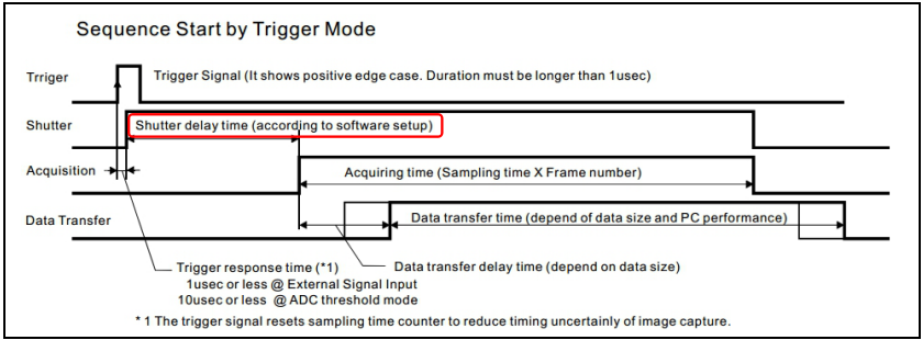
(1-3) Shutter delay (ms)
Set time between occurrence of trigger signal and start of data acquisition in msec. In this case, trigger signal means click operation of [RECORD] button in case of “[Trigger mode]=Software”, or external trigger signal input to the “External Input” terminal in the case of “[Trigger mode]=External”.
Since TTL signal (High output by default) is output from the "Shutter" terminal of the front panel at timing of trigger generation, it is possible to open (or turn on) shutter of excitation light source prior to data acquisition. Please set enough time to allow shutter to open completely (or light reaches set brightness).
(1-4) Min. shutter delay (ms)
Set minimum value of shutter delay. When a numerical value less than this is inputted to (3) [Shutter delay], it is automatically replaced with this value.
(2) Trigger
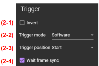
(2-1) Invert
If checked, trigger will be applied at negative edge of trigger signal.
(2-2) Trigger mode
Select the trigger source that determines the measurement start timing.
| Software | Software trigger. Acquisition begins when the [RECORD] button on the software is pressed. There are two possible uses. |
|---|---|
| External | External trigger. When you press the [RECORD] button, it is in “Waiting” state. Acquisition starts when the external signal (TTL) is input to the [External Input] terminal of the processor. |
| Ain1 w/ CMP | External trigger. When you press the [RECORD] button, it is in “Waiting” state. Acquisition starts when external analog signal (-1 to +1) is input to [Ain 1] terminal of the processor. Threshold voltage for the trigger signal can be specified by [Analog inputs]-[Trigger level (V)].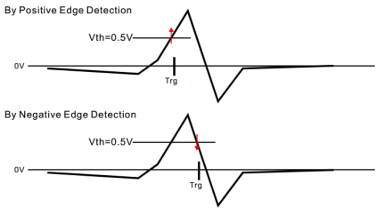 |
| Optional | External trigger. Trigger using an optional unit that will be developed in future (current version not supported). |
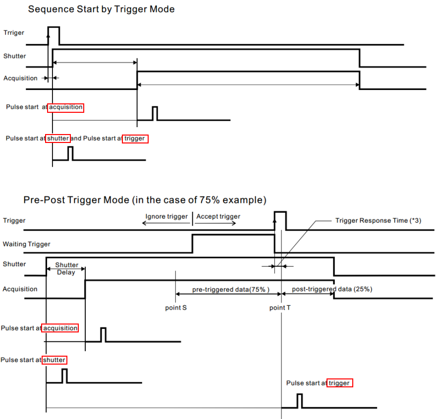
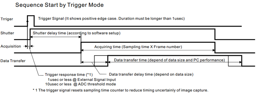
(2-3) Trigger position
| Start | From timing of trigger generation, acquisition starts in order of Shutter delay time→Acquisition. |
|---|---|
 | |
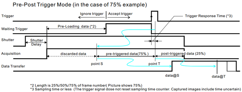
| 25% | Pre-Post trigger mode to record data before triggering. The trigger generation timing is 25% of acquisition length. |
| 50% | Pre-Post trigger mode to record data before triggering. The trigger generation timing is 50% of acquisition length. |
| 75% | Pre-Post trigger mode to record data before triggering. The trigger generation timing is 75% of acquisition length. |
 | |
(2-4) Wait frame sync
If checked, acquisition start signal waits for next frame sync pulse. If you do not know this setting, leave it checked.
(3) Analog inputs

(3-1) Enable
Controls ON/OFF of analog input to [Analog input1] and [Analog input2] on the front panel of MiCAM03 processor. When turned off, analog input is not recorded/saved, so data capacity is slightly reduced.
(3-2) Trigger level (V)
Specify threshold voltage when [Trigger mode]=”Ain1 /w CMP” is selected.
(4) Sequencer
This function can not be used in the EU countries, since the digital I/O port does not meet the EMC standards.
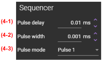
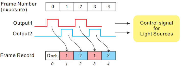
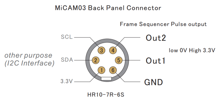
It is possible to output two kinds of LED lighting control signals from the digital I/O port on the back of the MiCAM03 processor. By using this “Sequencer” setting, intermittent excitation light irradiation that enables two kinds of LED light sources to be turned on alternately becomes possible. It can be used for applications such as two-wavelength excitation.
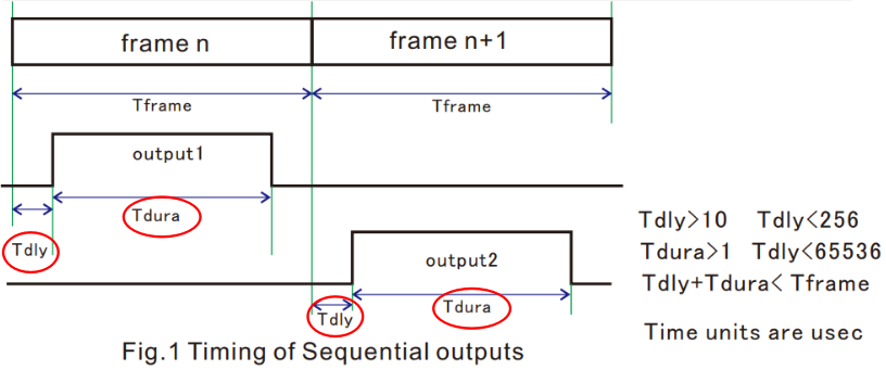
(4-1) Pulse delay (ms)
Set delay time between frame start timing and pulse start timing output from digital I/O terminal (= "Tdly" in the figure below).
(4-2) Pulse width (ms)
Set width of pulse output from digital I/O terminal (= “Tdura” in the figure below).
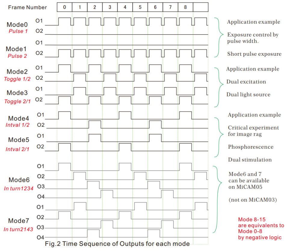
(4-3) Pulse mode
Select a pulse pattern from the following modes.
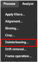
After acquiring the data, select [Process]-[Deinterleaving...] to automatically divide into odd and even frames and create two data.
(5) Other I/O

(5-1) Set Sync I/O as input
This is used to connect multiple MiCAM03 or to connect with another company's device and make it synchronous operation.
| OFF | MiCAM03 becomes “Master”. The frame synchronization signal (acquisition start timing of each frame) is always output from the [Sync I/O] port on the front of the processor . The voltage is 2.7V. |
|---|---|
| ON | MiCAM03 becomes "Slave". Output of frame synchronization signal is stopped, and external signal input can be accepted through the [Sync I/O] port. Internal frame timing signal is adjusted to synchronize with input signal. |
Synchronization of MiCAM03 image acquisition with external device
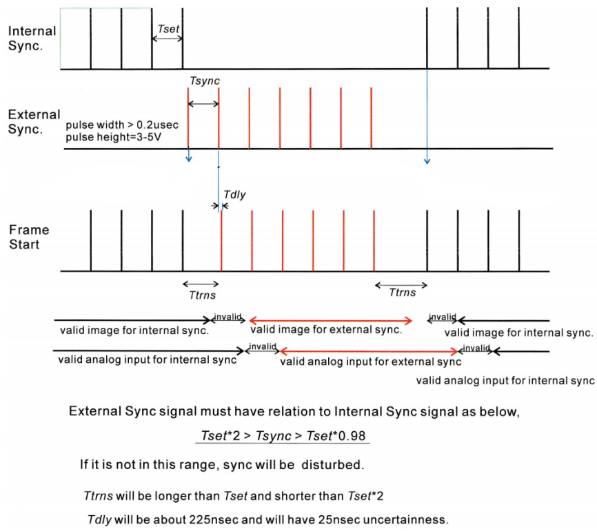
If frequency of frame timing signal from external device cannot be the same as frame rate (fps) of MiCAM03, please set Tsync in the range of “Tset*2 > Tsync>Tset*0.98”.
* Its possible that there are time lag in start timing of first frame, second frame and last frame, depending on input timing of external signal. If external signal is inputted in advance with start of image acquisition, this time lag can be avoided.
(5-2) Digital I/O (Hex)
Control input/output of the [Digital I/O] port on the back of the MiCAM03 processor.
(6) Pulse output
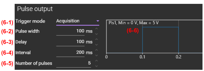
(6-1) Trigger mode
You can select from the following four settings.
| Disabled | Output from Pls1 and Pls2 turns OFF. |
|---|---|
| Acquisition | Pls1 and Pls2 start (delay time starts counting) at the start of image acquisition. |
| External | Pls1 and Pls2 start (delay time starts counting) when the external trigger signal is generated. |
| Shutter | Pls1 and Pls2 start (delay time starts counting) when shutter control signal is output. |
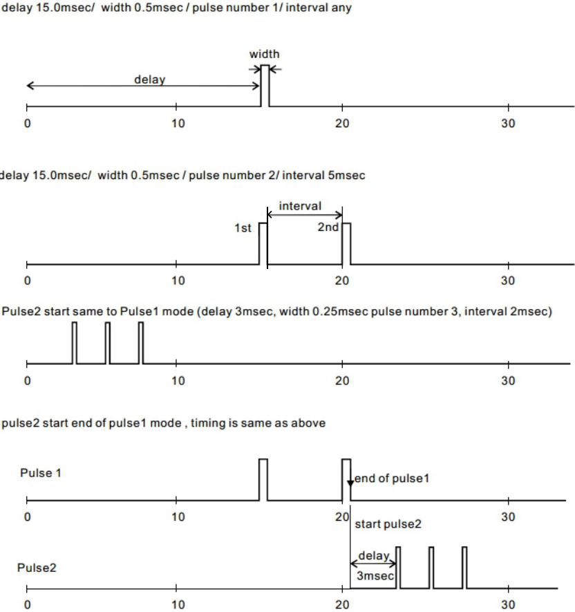
(6-2) Pulse width
Set width of one pulse output in millisecond.
(6-3) Delay
Set delay time before first pulse output starts in millisecond. The start of counting delay time depends on [Trigger mode] setting. Please refer to the timing chart below.
(6-4) Interval
Set pulse interval in milliseconds when two or more pulses are output. Pulse interval is from rising edge of previous pulse to rising edge of next pulse.
(6-5) Number of pulses
Set number of output pulses.
(6-6) Pulse pattern preview
Pattern of pulses output is displayed based on numerical values set in (6-2) to (6-5) . Turn mouse wheel button back and forth to zoom in / out the monitor image. If you right-click and select [Auto-scale], scale is automatically adjusted.
Example of Pulse Setting