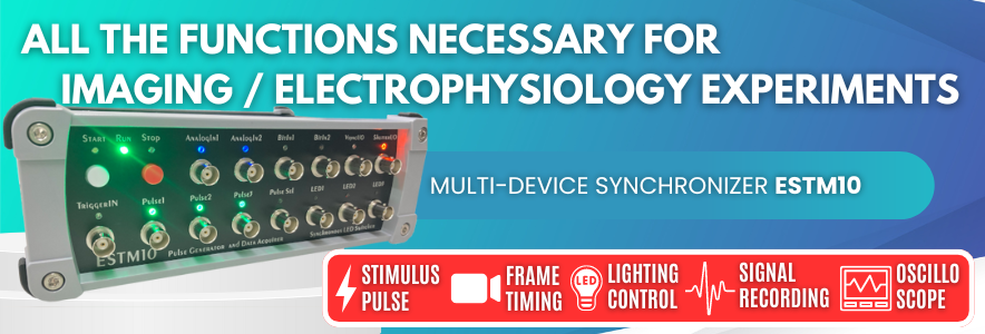
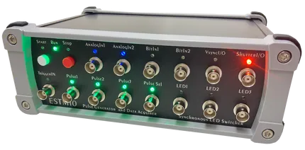
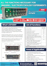
Multi-Device Synchronizer ESTM10
ESTM10 is an all-in-one system with built-in functions often used in biological imaging experiments and electrophysiology experiments, such as stimulus pulse output, acquisition timing control for camera, lighting control for LED light sources, biological signal recording, and digital oscilloscope, etc.
All built-in functions work in sync, so you can connect your peripherals to ESTM10 and have them fully synchronized without any special programming or hardware knowledge.
Multifunctional despite its small body. With this one unit, you can handle everything from student training in physiology to academic research.
List of Functions
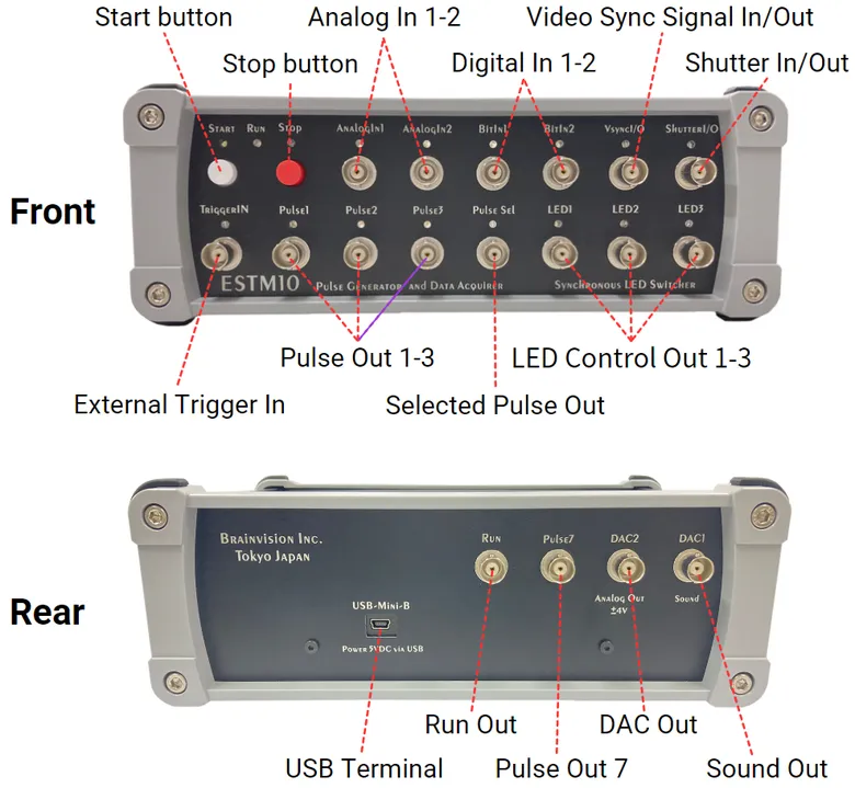
- Pulse output (5ch output from 8ch setting) *1)
- Analog output (1ch)
- Analog signal recording (2ch) *2)
- Digital signal recording (2ch)
- Camera frame sync signal input/output (1ch)
- LED light source signal output in synchronization with TTL signal input/output (3ch)
- Light source signal input/output at any timing (1ch)
- Digital oscilloscope *2)
- Sound monitor output *3)
- Supports multiple trigger sources (external TTL signal, button, external analog signal, software, internal repeat trigger)
- Powered by USB connection, operation and pulse settings are programmable from software
Areas of Application
- Electrophysiology experiments using brain/neurons or isolated heart and cultured cardiomyocytes
- Physiology student practical training using animal samples such as frogs
- GCaMP imaging for in vivo brain
- Voltage imaging and calcium imaging using neuronal and cardiac samples
Example of Use
- 1. As a multi-device synchronizer to perform biological imaging and bioelectrical signal recording in synchronization with camera, light sources, isolator, and electrophysiological amplifier
- 2. As an electrical stimulator in combination with an isolator
- 3. As a timing synchronization device for performing multi-wavelength excitation fluorescence imaging by connecting a camera and a light source with 2 to 3 wavelengths and turning on the light source alternately for each camera frame (e.g. GCaMP imaging with excitation at 405nm and 460nm, Fura-2 calcium imaging with excitation at 380nm and 340nm, etc.)
- 4. As a controller that connects to a light source or external device driven by TTL signals and turns on/off at any timing.
- 5. As a data logger that records bioelectrical signals through an electrophysiological amplifier.
- 6. As an oscilloscope to monitor bioelectrical signals passed through an electrophysiological amplifier.
- 7. As a sound monitor to monitor resistance values of an electrode inserted into a cell.
- 8. As a window discriminator that inputs an analog signal and outputs a pulse when input signal reaches a certain amplitude range in a certain time range.
- 9. As a pulse generator
Software
ESTM10 is controlled by software.
-
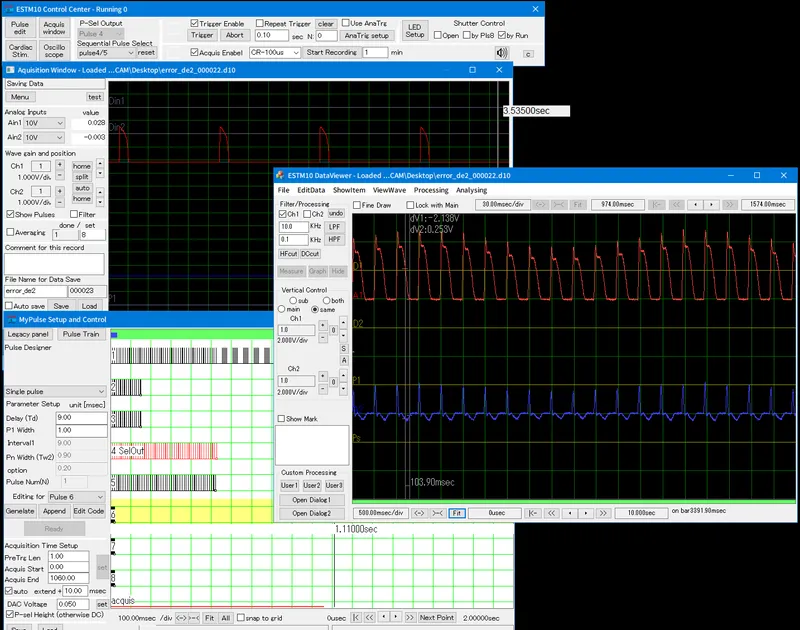 Software appearance
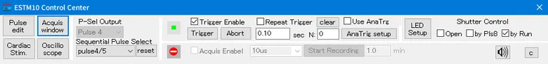
Control center
Centralizes access to each function and management of triggers and input/output functions. It is also possible to select pulse output channels and turn analog signal recording ON/OFF.
Window of each function
-
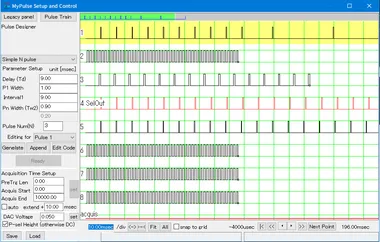 Setting for pulse output
-
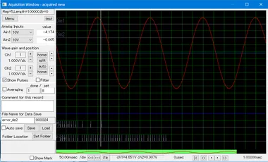 Analog signal recording
-
 Oscilloscope
-
 Setting for LED sequential lighting
Main features
1. Connection and synchronization with external devices
The diagram below is an example of an experimental setup combining an electrical recording with a recording electrode, electrical stimulation with a stimulation electrode, and 3-wavelength excitation fluorescence imaging that alternately switches 3 color LED light sources in synchronization with frames of a high-speed camera.
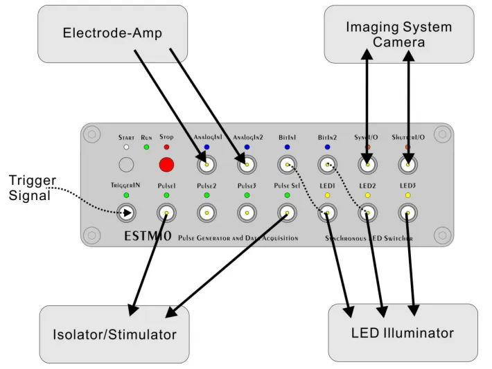
When imaging an animal or tissue sample with a camera, you may want to turn lights on and off according to start/end of imaging, perform electrical stimulation during imaging, and record electrical activity of samples all in synchronization. The challenge is that all these devices need to operate at the same time.
ESTM10 can output drive timing to cameras and stimulation devices, and simultaneously record signals captured by peripheral devices. So, you can solve the synchronization problem with one device.
-
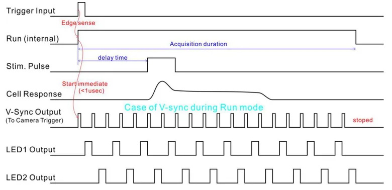 Example of external trigger mode settingCounting for preset “Run” time starts in response to an
external trigger (“Trigger Input”), and a stimulation
pulse (“Stim. Pulse”) is output after an arbitrary delay
time. Tissue response to this stimulation pulse can be
input and recorded at the ”Analog In” terminal.
Example of external trigger mode settingCounting for preset “Run” time starts in response to an
external trigger (“Trigger Input”), and a stimulation
pulse (“Stim. Pulse”) is output after an arbitrary delay
time. Tissue response to this stimulation pulse can be
input and recorded at the ”Analog In” terminal.
In addition, camera exposure start timing is controlled by “V-sync” signal that is output at the same time as start of “Run time”, and lighting signal to LED1 and LED2 is output in synchronization with “V-sync”.
2. Pulse output
This device can generate 8 channels of independent pulse trains in any pattern.
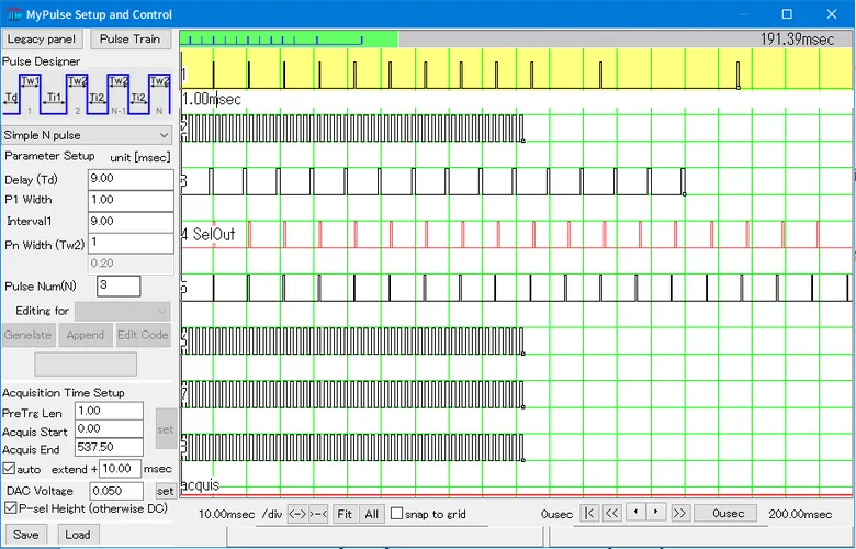
In addition to single pulses and continuous pulses, stimulation protocols used in cardiac research that require varied pulse intervals are also possible (e.g. S1-S2-S3-S4).
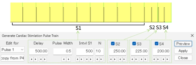
Stimulation protocol with changing frequencies and longer intervals is also possible.
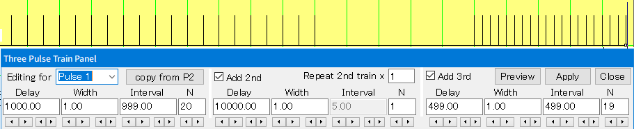
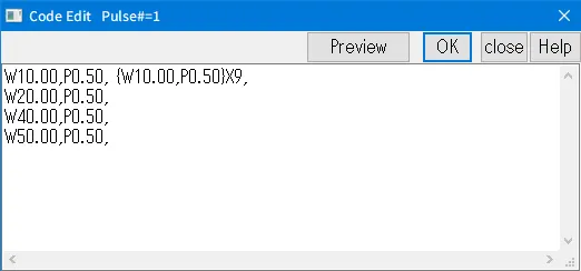
Basically, pulse patterns are set using GUI, but you can also specify pulse patterns using code editor.
3. Analog/digital signal recording
2ch analog inputs (1V or 10V) and 2ch digital inputs can be recorded and saved as files.
There is a basic mode that records up to 10 minutes at 100kHz, a pre-trigger mode that records signal input before trigger occurs, and a continuous recording mode that records up to 1 hour at 10kHz.
Saved data files can be opened with dedicated data viewer software, and in addition to display and data analysis, files can also be exported in CSV format.
-
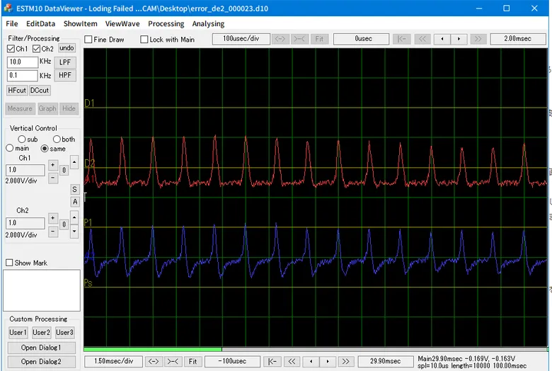 Data viewer software
4. LED lighting control function
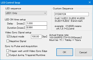
This function allows up to 3 LEDs to light up in any order in synchronization with the camera's frame signal (Video Sync Signal) input/output. Settings are input by simply specifying frame signal frequency, lighting delay time, lighting time, and lighting order.
Pulse train settings to control LED lighting are no longer necessary for fluorescence imaging even with 2-wavelength or 3-wavelength excitation.
-
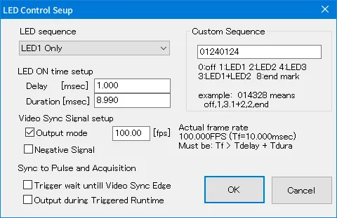 LED control setup
-
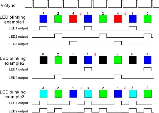 Example of LED lighting program
For rolling shutter cameras, exposure start timing after “V-Sync” input differs depending on pixel row, as shown in the figure below. Therefore, if you want to use different excitation light for each frame, it is necessary to turn on the LED light of a desired wavelength only during the time when all pixels are exposed. Please check the manual of each camera for difference in exposure start time depending on pixel row.
After setting the delay time from “V-Sync“ signal (Tdelay), lighting time (Tduration), number of LEDs, and lighting mode, ESTM10 will allocate and output lighting signal to LEDs automatically.
-
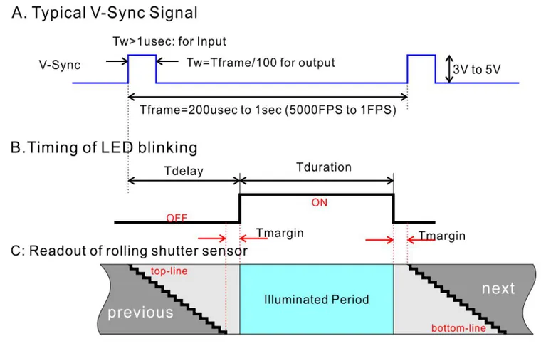 Relationship diagram between synchronization signal, LED
lighting timing, and rolling shutter sensor
Relationship diagram between synchronization signal, LED
lighting timing, and rolling shutter sensor
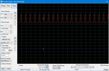
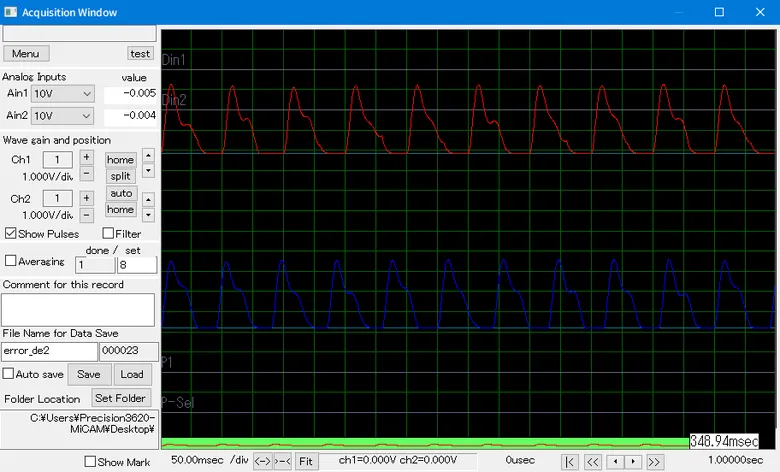
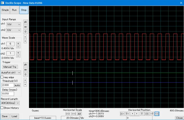
5. Oscilloscope
This function displays analog input signals in real time like a digital oscilloscope. “Single” mode and “Run” mode are available.
-
 Oscilloscope
Specifications
| Item | Specifications and recommended conditions | Memo |
|---|---|---|
| Dimensions / weight | 245mm (W) x 90mm (H) x 180mm (D) / 1.3kg | |
| Power-supply voltage | 5V | USB2.0 |
| Operating temperature | Room temperature (10-50 degrees) | |
| Environmental specifications/safety | RoHS3 compliant CE (LVD, EMC) standard compliant |
|
| Input terminal | Analog (2ch), Bit (2ch), Trigger (1ch) | Standard BNC |
| Output terminal | Pulse (5ch), Run (1ch), LED (3ch), Analog (1ch), Sound (1ch) | Standard BNC |
| I/O terminal | V-sync (1ch), Shutter (1ch) | Standard BNC |
| Electrical properties | ||
| Digital input terminal |
Input voltage: 0V/5V (-2V to 10V) Input resistance: 10KΩ (2.2KΩ to 10KΩ) Input capacity: 20pF (to 50pF) |
Voltage breakdown resistance |
| Digital output terminal |
Output voltage: 0V/5V (0V to 5.5V) Output resistance: 100Ω (to 120Ω) Output current: 5mA (4mA to 10mA) |
Current load resistance |
| Analog input terminal |
Input range: 10V (±100V) Input resistance: 110k/2.2MΩ (100kΩ to 2.3MΩ) Measurement accuracy: ±0.3% (error: ±1%) |
Voltage breakdown resistance |
| Analog output terminal |
Output resistance: 100Ω (to 12ΩΩ) Output current: 5mA (2mA to 10mA) |
Current load resistance |
| Analog output 1 | Output voltage: ±1V (±1.2V) | Non-calibration |
| Analog output 2 |
Output voltage: ±4V (±4.2V) Setting accuracy: ±0.3% (±0.1%) |
Accuracy after calibration |
| Timing characteristics | ||
| Trigger function |
- Trigger response time: 25.1μsec to 25.3μsec - External trigger response timing accuracy: -12nsec to 25nsec - Internal repeat interval: 10msec to 320sec - Analog trigger timing accuracy: ±10usec |
|
| Pulse generation function |
- Timing accuracy of pulse width and interval: ±1nsec - Timing accuracy between channels: ±6nsec - Configurable pulse width and interval: 10μsec to 167sec - Configurable continuous pulse train time: 10μsec to 596min |
8 channels |
| Acquisition function |
- Sampling interval (selectable):
10μsec/100μsec/500μsec - Time difference between channels: ±2.5usec - Frequency range (-6db value at 10μsec): DC 20kHz - Recordable time at 10μsec sampling: 1msec to 600sec - Recordable time at 100μsec sampling: 10msec to 6,000sec - Recordable time at 500μsec sampling: 50msec to 30,000sec |
Analog |
| LED control function |
- V-sync frame rate range: 1 to 5,000fps - LED delay time during V-sync input: 100nsec to 1μsec - Setting error/time accuracy when outputting V-sync: ±0.01fps/±12nsec - V-sync run control delay time: 100nsec to 1μsec - LED lighting time: 1μsec - (minimum time depends on fps) - LED delay/lighting time accuracy: ±±3nsec - Timing error between LED channels: ±3nsec |
Mainly when frame rate is more than 15.3fps |
| DAC2 function | Pulse delay and rise time: 1.5μsec to 2μsec | at 4V output |
| Noise characteristics | ||
| Analog input |
- Noise voltage at ±1V input/10μsec sampling: 0.5mV
(rms value), 2mV (P-P value) - Noise voltage at ±±1V input/100μsec sampling 0.1mV (rms value), 0.5mV (P-P value) - Crosstalk between channels 0.2% (after correction) |
14 bit |
| Analog output | Noise voltage: 2mV (rms value) | |
* This product is for research use only. * This product is made in Japan.
Flyer Download
-
Multi-Device Synchronizer ESTM10